Project: Light Weather
I made a temperature/pressure/humidity/gas sensor and general I/O interface for my "smart flat". This is a blog post / write-up of how and why I did that.

The hardware and firmware of V3 are open-source! Have a look at the GitHub Repo to see the design files and source code. You're welcome to install KiCad for the hardware, Platformio for the firmware, and have a go at building one, or modifying it however you feel like. Both of these tools are free, and they're open-source too.
Why would you do that?
It wasn't particularly necessary, but I quite like seeing all the data it records in various graphs. The aforementioned "smart flat" is a flat full of many zigbee and MQTT devices, including all the lights and a lot of smart plugs. Most of this is controlled by timers in Node-RED running on a Raspberry Pi, and from Zigbee buttons. When I'm out of reach of those buttons, I have a Telegram bot, or an Android app I wrote, but since I wrote it, the websocket in its backend keeps dropping out and I haven't been bothered to fix it yet.
The general idea with this project, as with most of the "smart flat", isn't that it's the best or easiest way to get anything done, or that off-the-shelf devices couldn't get the job done. Part of it is that I don't trust whatever cheap closed-source devices I'd get with access to my WiFi, despite how fun it may be to join a botnet. Another part is that completely over-engineering things that could be simple is good for learning new skills, and generally keeps your brain from going smooth. Since it's a hobby project with about one and a half users on average, there aren't really any consequences to over-cooking everything and making it take ages.
The main reason though, is that it's fun and satisfying to make something where the entire design is exactly for myself and my strange use case. It means that I know how the whole system works, and the only barrier to fixing/changing/adding any part of it is whether I can be bothered or find the time. None of the functionality is hidden from me in proprietary unchangable firmware blobs. The functionality isn't locked down to a use case chosen by some marketing department aiming to be just sufficient to as many thousands of people as possible.
That's the general idea. I'm not making a product to sell to the masses, I'm making something just for myself, and anyone else that visits my flat and has to be subjected to it.
The beginning
After a group project at university however many years ago, I was left with a collection of temperature, pressure, and humidity sensors. The project was about making a mesh network of battery-powered environmental sensors. Having only got as far as breadboarding the project, it felt wrong to leave the parts to become e-waste, so I decided to use the sensors on my house instead.
I started with just wiring the sensors with jumper wire to ESP8266 dev boards, and leaving them around the house connected to USB phone chargers. Using the Arduino core for them, I made them deep sleep for a minute, then wake up, take a measurement, then encode it as JSON and send it over MQTT to my Pi. The Pi then had a Python script that listened for these measurements, and added them to a Postrgres/TimescaleDB database running in a container. The Python script is on my GitHub, and it has an eye kept on it using the Supervisor Python project to make sure it gets resurrected if it dies. I've not checked the logs to see if it does die and get saved by Supervisor or if it just doesn't die, but either way it's been running for around three years now without noticeable outages.
The Pi software worked better than I'd expected, and the hardware worked fine, but early this year, I decided it just looked too ugly.
Light Weather - Version 1

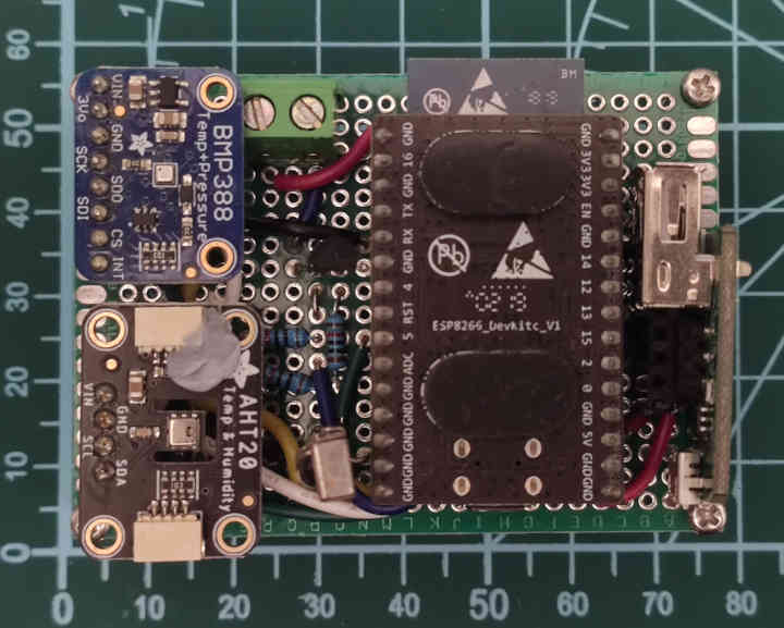
While I may have paid more attention to the programming modules, my degree was in electronic and computer engineering, and having a rats nest of rainbow jumper wires in view of the whole flat was at least a little embarrassing. I decided to solder the project together on some perfboard.
While laying out the ESP8266 DevKit-C, Adafruit BMP388 temperature/pressure sensor module, and Adafruit AHT20 temperature/humidity sensor module on the perfboard, I noticed that the place I had the current system plugged in on the shelves was next to some fairy lights and a USB lamp, and that those should be fairly easy to control. I had a USB power switch board (made by 8086 Consultancy) left over from an old Pi project, and it seemed perfect for controlling the USB lamp. It was a breakout for a SIP32508 load switch IC, which acts as a high-side switch suitable for 5 V that can be controlled from a 3.3 V input pin. For the fairy lights, they originally ran on 3 AAA batteries for 4.5 V, and from having a go with a variable PSU, they seemed to draw 110 mA at 5 V, and more importantly didn't pop. I added a through-hole NPN BJT (2N2222) to the circuit as a low-side switch for the fairy lights.
It was then easy to make the ESP8266 code listen for MQTT messages that could make it toggle IO pins. The code had to have the deep-sleep removed so it wouldn't miss messages, but the deep-sleep feature was mainly left behind from its original purpose of being battery powered anyway.
MQTT control was good for timers, and for when I was in arms reach of one of my Zigbee buttons, but for more convenience I added an IR receiver so that a generic IR remote could control its lights. I then made it output the remote control button presses over MQTT, so that I could connect them to the smart lights etc. through Node-RED.
The project now had lots more functionality, and did look less ugly than what came before, but to call it not ugly would be a stretch. It looked like enough of a project to be worthy of a name though, and since it controlled lights and measured weather, and I was listening to Weather Report while programming it, it was given the name Light Weather.
Light Weather - Version 2

Less ugly was a definite improvement, but I felt I could do better. A lot of the force behind this project was how prominently it was placed in the room, which made its messy construction a lot more noticeable.
I watch a few electronics channels on YouTube, and when they make a project, the last step always seems to be making a custom PCB for it. I would too if I was offered as much sponsorship money as them. Despite it being product placement, the custom PCBs did look a lot nicer than anything I'd made, so I decided to have a go. Chinese PCB manufacturers are surprisingly cheap, even accounting for shipping. After this, I installed SponsorBlock to protect me from buying anything based on product placement again, we'll see how well it works.
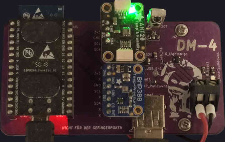
At uni, I had to choose between making a C++/Qt GUI program for viewing 3D models, and making a switch-mode power supply PCB, and I chose the former, so I had no experience of PCB design there. On a work placement I had designed a PCB, but it was a capacitor bank that took three-phase power straight out of the rectifier, so that comically thick PCB didn't have much in common with this project. As I had little experience, I decided to make the PCB as simple as possible, by only making minor changes to my previous design. I kept the ESP8266 and sensors on their development boards, but put the SIP32508 load switch IC directly on the PCB, along with a logic-level MOSFET instead of the 2N2222. I had wanted to use a MOSFET in version 1, but I couldn't find one that was through-hole and operable with 3.3 V logic to make the implementation simple. The AO3416 was suitable, but only in the surface-mount SOT23 package.
The PCB design was extremely simple, since it was mostly just replacing
the perfboard and tangled wiring, nothing on it needed to switch at
high frequencies or carry large currents. Learning enough KiCAD to make
this was surprisingly easy, I didn't even have to resort to YouTube
tutorials. I was pretty good at resisting the temptation of
feature-creep, knowing that it was my first real PCB for a hobby
project, it was all quite new and unproven. I said it was easy, but the
first time I sent the PCB off to be made, they emailed me back saying
I'd forgotten to add the actual shape of the PCB for them to cut it
down to in the Edge.Cuts layer, which was mildly
embarrassing.
I purchased AliExpress' finest reflow hot plate and solder paste, lined up the components, and cooked it on my kitchen table with all the windows open. To my surprise, the whole thing worked first time, with the only slight mistake being that the IR receiver had the wrong footprint, so I had to bend the middle leg around to become the left leg.
Perfect, job done, can put the project to bed. Although I'd made it look a bit more professional than before, the fact that I was still using off-the-shelf dev boards for the MCU and sensors was quite noticeable, to me anyway.
Light Weather - Version 3

With my new-found skill of ordering PCBs off the internet, I decided to try making something that I actually enjoyed looking at. For me, that meant no dev boards sticking up showing that their contents were too difficult, and having the components spaced somewhat close to each other, since soldering densely packed components wasn't anywhere near as hard as I'd expected when I was laying out the last version.
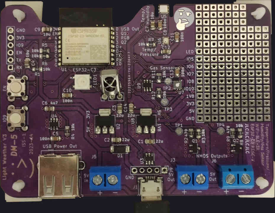
So I started a new project in KiCAD, and ordered some ESP32-C3 WROOM modules from LCSC. These are modules that include the MCU, crystal, flash, and a PCB antenna. They're very compact, and are soldered straight to the main PCB. I resisted the temptation to go straight to the raw chips and get my head around tuning a 2.4 GHz PCB antenna, since plenty of commerical products just use these modules too. So far I have continued to resist making version 4 to do this. The features I did not resist adding were a gas sensor, and of course an addressable RGB LED, but that last one should go without saying.
You wouldn't think it from reading this, but of my hobby projects, this might be the one to survive the furthest through development in the war against feature creep. It has killed many an innocent project.
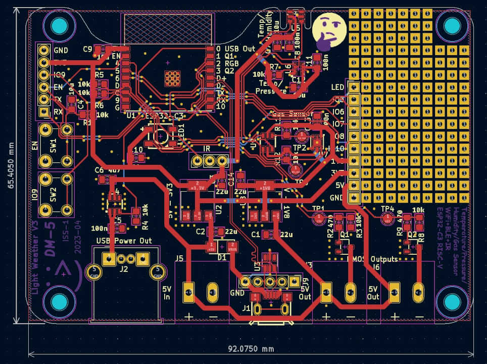
I decided to pay a bit more attention when designing the PCB for this version, and make it a nice shape that clears out of the way of the WiFi antenna. I also made the ground plane on the back much more contiguous and less chopped up by traces. I won't pretend to have a good understanding of the wizardry that is EMC , but as I understand it, this is what a wise layout artist would do.
Another fun technical bit was wiring the USB differential pair from the connector to the module, which I interestingly put on complete opposite sides of the board. I got to use KiCADs feature of adding precisely the right amount of wiggle to one trace to make the two traces exactly the same length. This is good practice, but in the real world I tested using raw USB with an ESP32-C3 module deadbugged into a breadboard and that worked fine, so USB 1 at the speed of serial must be very forgiving if it can survive that treatment.
To make future development easier, I took a large area of free space on the board and turned it into perfboard by adding a lot of unconnected through-hole footprints. I ordered the boards, this time with a stencil for the solder paste, which increased the shipping cost by quite a bit.
When soldering it, I had assumed the hardest part would be the 8-pin DFN package of the BMP280 that was 2 by 1.5 mm, but it was actually the micro USB connector that gave me the most soldering trouble. Once everything was soldered on, nothing would power up, and the 1.8 V regulator was feeling extremely toasty. After poking around for a while, I checked the schematic and I'd connected VDD and VSS (positive and negative) of the SGP30 gas sensor backwards, so I had to desolder it. Sadly the 6-pin DFN package was too difficult to bodge, so I had to order a second revision. To be fair, three versions of the project that worked "first time" would have been asking a bit much.
In the time it took for the second issue to arrive with the cheapest shipping, I had ported the firmware to the ESP32 C3 and added the new features except for the gas sensor. Conveniently for me, the Adafruit libraries for their breakout boards worked the same for the raw ICs, so development was very easy. The code was quite straightforward, a class that looked after each device e.g. the LED or WiFi, and some queues to coordinate between them. The sensor readings were taken once a minute, and then on the fifth minute, the code would take the median value of the 5 and send that over MQTT.
The code could be re-written to use a lot less of the resources of the ESP32, but even the cost-optimised C3 has way more resources than I can waste. This loosely-coupled approach to the firmware was helpful as it meant across the various versions of the project, and some other projects I've done, the parts of the code are pretty much copy-pastable between them. This is another fun benefit of making a project to be used mostly by me, I can be wasteful to make things easier for myself as much as I like.
Conclusion
The project has successfully sat there on my shelves for a few months now, and seems to have worked without any outages the whole time. I'm counting the fact that I've resisted making version 4 and kept using version 3 as a success. Many of my projects have not been so lucky.
I enjoyed making it, and it made me learn a new skill too. I don't think making your own is for everyone, but I'd recommend having a go at making my version 0 or 1 to anyone as it could be done in an afternoon. Unlike my usual software projects that usually run out of sight on my Pi, having a semi-professional looking product that you can pick up and hold is very satisfying.
Despite all this talk of not making version 4, I am thinking about putting an I2C OLED screen on the prototyping area so that I can make a standalone version that anyone could use. I've got a screen that's the exact right shape, so it seems rude not to. Since it shouldn't involve changing the PCB, it counts as still being version 3 in my opinion.
A noticeable downside of this project is that it's made me look at all my previous electronics projects and wonder how much better they'd look if I made them a custom PCB. I'm too used to software projects that don't cost anything.